

In the process, the study's unifying definition of reflection coefficient allows and facilitates one consistent interpretation of the Smith chart among the possible Γ definitions, including Kurokawa's.

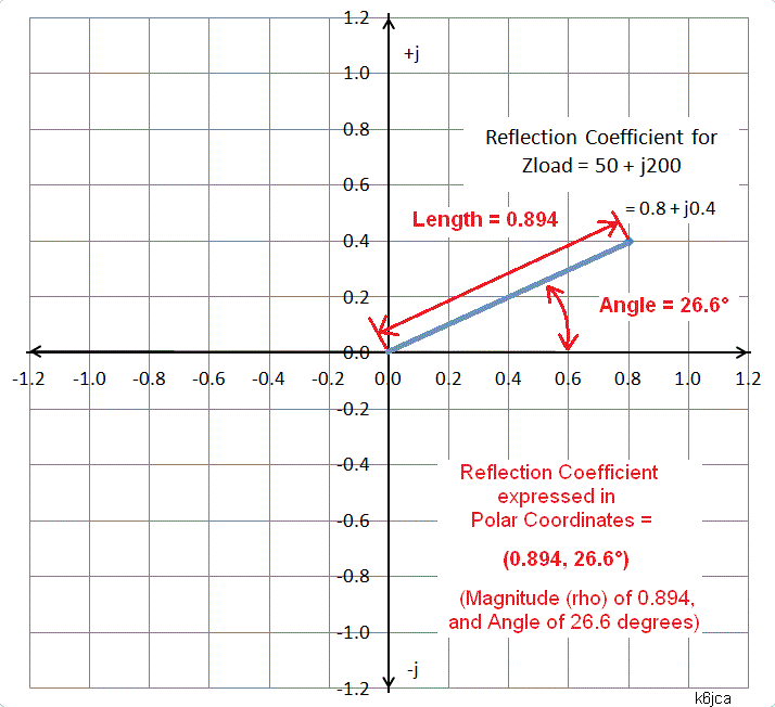
To plot this, one may use the circumferential (reflection coefficient) angle scale to find the graduation and a ruler to draw a line passing through this and the centre of the Smith chart. the center of the chart and the constant reflection coefficient circle, read zL -j0:425. when using an arbitrary complex waveform ratio of voltage to current. A point with a reflection coefficient magnitude 0.63 and angle 60 represented in polar form as, is shown as point P 1 on the Smith chart. As a logical consequence of the previous discussion, a new definition of reflection coefficient is proposed and validated: the apparent differences stemming from either the standard or Kurokawa's definition of reflection coefficient Γ are easily interpreted as particular cases of the proposed transformation. Townsend THE SMITH CHART AND ITS APPLICATIONS TRANSMISSION LINES THE. Example: 50 line connected to 75+j10 load impedance. 3.The VSWR is read where the circle crosses the real axis on right side. 2.Draw a circuit centered on the Smith chart that intersections this point. The study starts off from the Kurokawa's definition of reflection coefficient to discuss the required steps to map Z into Γ and highlights the differences that exist between Kurokawa's and the standard Γ definition. 1.Plot the normalized load impedance on the Smith chart. This study develops a unifying theory that defines a single transformation from the impedance Z to the reflection coefficient Γ plane independently of the impedance normalisation in use and the real or complex nature of the characteristic impedance Z 0.


 0 kommentar(er)
